From idea to market-ready product, our NPI solutions make every stage easier, faster. Discover How We Help

Views: 222 Author: Tomorrow Publish Time: 2025-12-04 Origin: Site
Content Menu
● Understanding CNC Milling Basics
● Cartesian Coordinates And Work Offsets
● Absolute And Incremental Programming
● M-Codes And Auxiliary Functions
● Feeds, Speeds, And Tool Data
● Programming Workflow With CAM
● Manual G-Code Programming Steps
● Toolpaths And Machining Strategies
● Workholding And Setup Considerations
● Tool Length And Diameter Compensation
● Safety, Dry Runs, And Simulation
● Advanced Programming Techniques
● Debugging And Optimizing Programs
● From Beginner To Advanced Programming
● FAQ
>> 1: What Is The Difference Between G-Codes And M-Codes?
>> 2: Do I Need CAM Software To Program A CNC Milling Machine?
>> 3: How Do I Choose Feeds And Speeds?
>> 4: What Is Work Offset In CNC Milling?
>> 5: How Can I Practice CNC Programming Safely?
Programming a CNC milling machine involves creating precise instructions using G-code and M-code to control tool movements, speeds, and machine functions for accurate part production. This process ranges from manual coding for simple parts to advanced CAM-generated programs for complex geometries.

CNC milling machines remove material from a workpiece using rotating cutters guided by computer-controlled axes. These machines typically feature X, Y, and Z linear axes, with optional rotary axes for multi-axis operations. The control system interprets programs line by line, executing rapid traverses, cutting feeds, and auxiliary actions.
Key components include the spindle, tool changer, table or fixture, and controller. Programmers must account for machine rigidity, power, and accuracy limits when planning operations. Understanding these basics ensures programs maximize machine potential without exceeding capabilities.[3][11]
The Cartesian system defines positions with X for left-right, Y for front-back, and Z for up-down movements. Absolute coordinates reference a fixed origin, while incremental coordinates measure from the current position. Programmers select modes with G90 for absolute and G91 for incremental.
Work offsets like G54 through G59 store multiple origins for fixtures or repeated parts. Operators set these by edge-finding or probing, ensuring the program origin aligns with the physical workpiece. Proper offsets prevent crashes and maintain tolerances across setups.[11][12]
Absolute mode simplifies visualization since all points relate to one origin, ideal for contours and profiles. Incremental mode excels in loops, patterns, or adjustments from prior positions. Switching modes mid-program requires clear documentation to avoid disorientation.
For example, drilling a bolt circle might use incremental for angular steps after positioning the center absolutely. Most controls default to absolute, but verifying mode prevents cumulative errors in repetitive sections.[3]
G00 commands rapid positioning without cutting. G01 performs straight-line feeds at controlled rates. G02 and G03 create clockwise and counterclockwise arcs, requiring an I, J, K center offset or R radius.
Plane selection codes G17 (XY), G18 (XZ), and G19 (YZ) define arc and cycle planes. Canned cycles like G81 (drill), G82 (drill with dwell), and G83 (peck drill) condense multi-step operations into single lines with parameters for depth, peck, and retract.[11][3]
M03 and M04 start the spindle clockwise or counterclockwise, with M05 stopping it. M08 and M09 control coolant flood on and off. M06 handles tool changes, M00 programs optional stops, and M30 ends and rewinds.
These non-modal codes execute immediately, coordinating with G-codes for complete cycles. Sequencing prevents issues like dry cutting or spindle crashes during changes.[3]
Spindle speed uses S values in RPM, calculated as surface speed divided by tool circumference. Feed rates via F codes balance chip load, power, and finish. Tool tables store T numbers with D for diameter compensation and H for length.
Start with manufacturer charts, adjusting based on sound, chips, and wear. High-speed steel tools suit softer materials, while carbide excels in hard metals at higher parameters.[3]
CAM imports CAD models, sets stock, work offsets, and tools. Strategies include adaptive clearing for roughing, steep/shallow for 3D, and rest machining for efficiency. Post-processors output controller-specific code.
Verification simulates cuts, checking collisions and air time. CAM reduces errors but requires understanding for edits.[2][11]
Begin with header: O1234 (program number), G20/G21 (inch/metric), G90, G54. Safety line: G28 G91 Z0 (home Z), G90. Tool call: T1 M06, G43 H01 (length comp), S2000 M03.
Approach: G00 X0 Y0 Z1.0, G01 Z-0.1 F10. Cut with G01/G02/G03. Retract: G00 Z1.0, M05, M09, M30. Comments clarify intent.[11]
Rough with 50-70% stepover, deep axial depths. Finish with 5-10% stepover, shallow passes. Climb milling reduces burrs; conventional aids entry.
Ramping or helix entry avoids plunge loads. High-speed paths use trochoidal milling for constant load, extending tool life.[4]
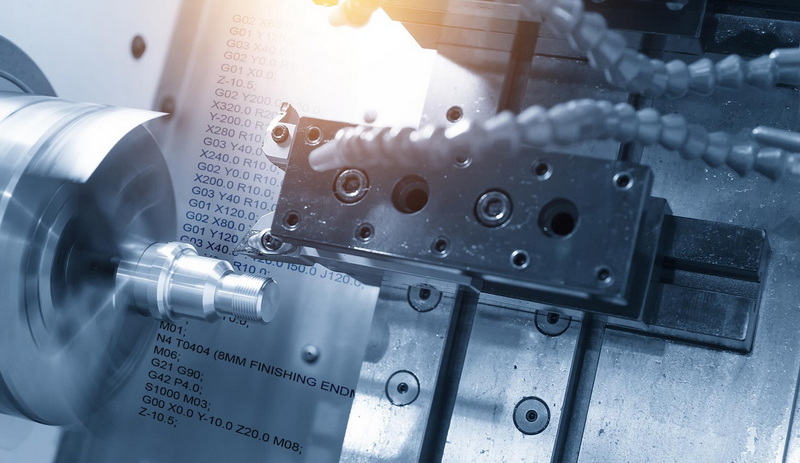
Vises secure with soft jaws; toe clamps distribute force. Fixtures repeat accurately for batches. Probe offsets or use 3-2-1 method.
Verify with test indicators, adjusting for runout under 0.001 inch.[3]
G43 activates length comp (H), G41/G42 radius (D left/right). Leads smooth entry. Cancel with G40/G49.
This adapts programs to wear or swaps without recalculation.[11]
Single-block tests motions. Graphics verify paths. Dry run at height checks limits.
Start cuts conservative, monitoring vibration.[2]
Parametric programming uses variables for families of parts, like #100=DIAMETER. Heidenhain Q-params or Fanuc macros compute loops dynamically.
Subprograms (M98 P999) repeat sections, reducing code. Custom cycles for spheres or patterns invent efficiencies.
Macros add logic: IF statements branch, WHILE loops iterate. This automates probing, adapts to measurements.[1][2]
High-speed machining employs look-ahead for smooth acceleration. 4/5-axis tilts tools for undercuts, using G68.2 or TCPC.
Optimization minimizes rapids, groups tools, sequences by depth.[1][4]
Search errors with alarms. Edit feeds for chatter. Macros probe and adjust.
Constants (Fanuc #3000+) store formulas. Verify post-simulation.[2]
Progress from 2D pockets to 3D surfaces, then multi-axis. Master modals, locals.
Practice edits CAM output for insight.[1]
Mastering CNC milling programming builds from basics like coordinates and codes to advanced parametrics and strategies. Precise setups, simulations, and optimizations yield efficient, reliable parts. Continuous refinement elevates production quality and speed.
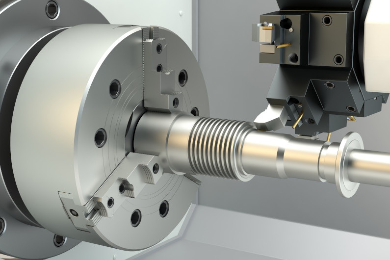
G-codes handle motion and modes like feeds and arcs. M-codes manage auxiliaries such as spindle and coolant.[3]
CAM automates complex paths but manual suits simples. Hybrids optimize both.[2]
Use charts, adjust for material and rigidity. Monitor chips.[3]
Stored origins for setups. Probe to set accurately.[11]
Simulate, single-block, dry run. Verify offsets.[2]
[1](https://www.ijert.org/research/advanced-programming-techniques-for-a-cnc-milling-machine-IJERTV9IS090227.pdf)
[2](https://www.datron.com/resources/blog/hacks-for-computer-numerical-control-cnc-programming/)
[3](https://rosnokmachine.com/cnc-machine-programming/)
[4](https://tmc-technologies.com/cnc-programming/)
[5](https://shamrockprecision.com/mastering-cnc-milling-basics-techniques-and-applications/)
[6](https://www.youtube.com/watch?v=Qqg-aoVIs_8)
[7](https://www.goodwin.edu/enews/cnc-machining-techniques/)
[8](https://www.youtube.com/watch?v=4xNMYLPE_jM)
[9](https://www.cnccookbook.com/cnc-programming-g-code/)
[10](https://www.youtube.com/watch?v=hJNCExRvxMk)
[11](https://www.cnccookbook.com/cnc-programming/)
[12](https://www.americanmicroinc.com/resources/beginner-guide-cnc-programming/)


