From idea to market-ready product, our NPI solutions make every stage easier, faster. Discover How We Help

Views: 222 Author: Tomorrow Publish Time: 2025-11-24 Origin: Site


Content Menu
● Understanding CNC Turning Basics
● Key Parameters for Cycle Time Calculation
● Factors Influencing Cycle Time
● FAQ
>> 1. What is the formula to calculate CNC turning cutting time?
>> 2. How does setup time affect CNC turning cycle time?
>> 3. What parameters influence spindle speed calculation in turning?
>> 4. How can CNC turning cycle time be optimized?
>> 5. Why is including non-cutting times important in cycle time estimation?
Calculating CNC turning cycle time is vital for optimizing machining efficiency, estimating production costs, and improving scheduling accuracy. Cycle time refers to the total time required to complete one turning operation, encompassing all cutting strokes, tool changes, and auxiliary tasks. Accurate calculation of cycle time helps in resource planning and achieving consistent manufacturing throughput.

CNC turning is a machining process where a rotating workpiece is shaped by a stationary cutting tool to remove material and create cylindrical parts. The cycle time includes actual cutting time, machine movements, tool changes, and non-machining activities such as loading and unloading. Ensuring all these components are included is critical for precise cycle time calculation.
To calculate CNC turning cycle time effectively, you need to consider:
- Cutting Length (L): Total distance the tool travels to complete the cut, including approach and overtravel.
- Feed Rate (f): The rate the tool advances per revolution of the workpiece, usually in mm/rev.
- Spindle Speed (N): Rotational speed of the workpiece spindle in revolutions per minute (RPM).
- Setup Time: Time required to prepare the machine and fixture.
- Tool Change Time: Time consumed changing cutting tools.
- Rapid Movement Time: Non-cutting tool movements between operations.
- Idle Time: Waiting or loading time without machine cutting.
The fundamental formula to estimate cutting time in CNC turning is:
$$
T_{\text{cutting}} = \frac{L}{f \times N} \times 60
$$
Where:
- $$L$$ is cutting length in millimeters.
- $$f$$ is feed rate in mm/rev.
- $$N$$ is spindle speed in RPM.
- Multiplying by 60 converts time to seconds if feed and speed are per minute units.
For multiple passes, multiply the cutting time by the number of passes. This represents the pure cutting time without setup and overhead.
Total cycle time adds non-cutting operations:
$$
T_{\text{total}} = \frac{T_{\text{setup}}}{\text{Batch size}} + T_{\text{cutting}} + T_{\text{tool change}} + T_{\text{rapid}} + T_{\text{idle}}
$$
- Setup is divided by batch size because it is shared across units.
- Tool changes and rapid traverses add extra duration.
- Idle and manual handling times reflect real manufacturing conditions.
Spindle speed depends on cutting speed and workpiece diameter:
$$
N = \frac{1000 \times V}{\pi \times D}
$$
Where:
- $$V$$ is cutting speed in meters per minute.
- $$D$$ is the average diameter of the workpiece in millimeters.
Calculating $$N$$ ensures the cutting tool operates at optimal speeds for material and tool type.
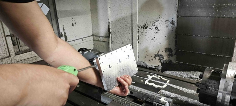
Several factors affect the CNC turning cycle time:
- Material Type: Hard materials require slower speeds and longer cuts.
- Tool Geometry and Quality: Sharp, specialized tools enable faster cutting and better chip control.
- Machine Capabilities: High acceleration and deceleration reduce positioning time.
- Programming Efficiency: Optimized tool paths minimize idle time and rapid movements.
- Setup and Tool Change Efficiency: Fast setups and tool changes lower overall cycle time.
- Batch Size: Larger batches reduce per-piece setup time impact.
Maximizing efficiency and minimizing cycle time can be done by:
- Using advanced CAM software: Programs that automatically optimize tool paths and speeds increase efficiency.
- Applying iMachining or high-efficiency machining strategies: These adjust feed rates dynamically and maintain constant cutting forces to speed up material removal and extend tool life.
- Reducing tool change count: Grouping operations to minimize changes.
- Automating part loading and unloading: Using robotics to work in parallel with machining.
- Optimizing machine acceleration/deceleration: Fine-tuning to reduce non-cutting movement time.
- Implementing tool monitoring systems: Dynamically adjusting cutting parameters to keep optimal conditions.
1. Calculate spindle speed based on workpiece diameter and cutting speed.
2. Measure cutting length including all passes.
3. Determine feed rate per tool and material guidelines.
4. Use the core formula to calculate cutting time.
5. Sum tool changes, rapid movements, and setup times.
6. Divide setup time by batch size to find time contribution per part.
7. Add all to get total cycle time for one part.
8. Review and optimize parameters iteratively to reduce time.
Calculating CNC turning cycle time involves combining cutting length, feed rate, spindle speed, and supplementary machine operation times. Including setup, tool changes, and idle periods ensures a realistic cycle time estimate. Continuous optimization through programming, tooling, and automation can significantly reduce cycle time, improving manufacturing efficiency and lowering costs.

The fundamental formula is $$T = \frac{L}{f \times N} \times 60$$, where $$L$$ is cutting length, $$f$$ is feed rate, and $$N$$ is spindle speed.
Setup time is spread over the batch size, so larger batches reduce setup time contribution per part, decreasing overall cycle time.
Spindle speed depends on cutting speed and average workpiece diameter, calculated as $$N = \frac{1000 \times V}{\pi \times D}$$.
Optimizing includes using advanced CAM software, reducing tool changes, automating part handling, and employing high-efficiency tool paths.
Non-cutting times like tool changes, rapid moves, and idle times significantly affect total production time and accurate scheduling.
[1](https://www.cgstool.com/blog/cnc-machining-optimizing-cycle-times/)
[2](https://www.sigmatechnik.com/cnc-factory/optimizing-cnc-turning-cycle-time-a-practical-guide)
[3](https://www.cncyangsen.com/strategies-to-drastically-reduce-cnc-machining-cycle-time)
[4](https://www.mmsonline.com/articles/how-to-reduce-cycle-times-by-70-and-more-on-your-existing-cncs-and-dramatically-improve-tool-life-too)
[5](https://www.reddit.com/r/Machinists/comments/ps0y1q/what_is_the_best_machining_cycle_time_reduction/)
[6](https://www.youtube.com/watch?v=SmwMICwVgr0)
[7](https://www.practicalmachinist.com/forum/threads/reducing-cycle-times.288098/)
[8](https://www.americanmicroinc.com/resources/cnc-machining-cycle-time-calculation/)
[9](https://www.youtube.com/watch?v=Re_LT92a2MA)
[10](https://mechmatrix.in/how-to-reduce-cycle-time-without-reducing-tool-life-in-cnc-machining/)


