From idea to market-ready product, our NPI solutions make every stage easier, faster. Discover How We Help

Views: 222 Author: Tomorrow Publish Time: 2026-01-13 Origin: Site


Content Menu
● Overview of CNC Axes and Coordinate System
● The Primary Axes in CNC Turning Machines
>> 1. X-Axis – Radial Movement
>> 2. Z-Axis – Longitudinal Movement
>> 3. C-Axis – Angular Positioning
● Extended and Auxiliary Axes in Multi-Axis CNC Turning
>> 4. Y-Axis – Vertical Linear Motion
>> 5. B-Axis – Tool Head Rotation
>> 6. A-Axis – Secondary Rotary Axis (Optional)
● Classification of CNC Turning Machines by Axis Count
● Differences Between CNC Turning and CNC Milling Axes
● The Role of Spindle and Turret in Axis Control
● Advantages of Multi-Axis CNC Turning
● Industrial Applications of Multi-Axis Turning
● Factors to Consider When Choosing a CNC Turning Axis Setup
● Future Trends in CNC Turning Axes
● FAQ
>> 1. What is the difference between X and Z axes in CNC turning?
>> 2. What does the C-axis do in a CNC lathe?
>> 3. What is the purpose of the Y-axis in turning?
>> 4. How many axes can a CNC lathe have?
>> 5. Why is multi-axis CNC turning beneficial to manufacturers?
Computer Numerical Control (CNC) turning is a cornerstone process in modern manufacturing, transforming raw materials into accurate, high-quality components. By automating movements along defined axes, CNC turning enables precise control over cutting operations, ensuring dimensional consistency and repeatability at scale.
Understanding which axes are there in CNC turning machines is crucial for machinists, engineers, and manufacturers aiming to optimize production quality and efficiency. Each axis—whether in a basic 2-axis lathe or an advanced 5-axis turning center—plays a specific role in shaping, contouring, and finishing parts.
This article offers a deep dive into the different axes involved in CNC turning, their unique functions, axis combinations across machine types, and how multi-axis systems enhance operational flexibility and precision.

CNC turning is a subtractive machining process that removes material from a rotating workpiece using a stationary or moving cutting tool. The material is fixed on a spindle and rotated at high speed, while the cutting tool advances linearly or radially based on programmed coordinates. The process is controlled by a digital code, commonly known as G-code, which governs tool movement, feed rate, spindle speed, and depth of cut.
Typical CNC turning operations include:
- Facing: Flattening the workpiece's front surface.
- Taper turning: Producing cone-like shapes.
- Thread cutting: Creating internal or external threads.
- Grooving: Cutting slots or recesses.
- Parting: Separating a finished piece from the stock bar.
CNC lathes are widely used in industries ranging from medical to automotive thanks to their ability to create symmetrical, cylindrical, or conical parts with extreme precision and minimal manual intervention.
CNC turning machines operate based on a Cartesian coordinate system, which uses X, Y, and Z axes to control movement in space. The spindle's rotational motion forms the central reference point around which linear and angular motions occur.
Each axis represents a direction of movement:
- Linear axes: X, Y, Z
- Rotary axes: A, B, C
In CNC turning, the X and Z axes are fundamental. The X-axis controls radial motion, and the Z-axis controls longitudinal motion along the spindle. Additional axes such as C, Y, and B are incorporated in advanced systems for secondary operations like milling and drilling.
The X-axis controls the cutting tool's movement toward or away from the centerline of the rotating workpiece. This motion adjusts the cutting radius and directly influences the final diameter of the finished component.
For example, when machining a shaft, the X-axis defines its outer diameter. Fine-tuning X-axis coordinates is essential for achieving dimensional tolerances within microns, especially in precision machining applications such as aerospace and hydraulics.
The Z-axis controls tool movement parallel to the spindle axis. Movements along this axis determine part length and surface contours. The Z-axis is responsible for shaping operations like turning, threading, grooving, and contour finishing.
In automated production, Z-axis motion integrates with feed rate control to maintain optimal chip load and surface finish, reducing tool wear and improving overall machining efficiency.
The C-axis allows controlled spindle rotation. This enables the tool to machine features at specific angular intervals—perfect for tasks like slotting, flat milling, or drilling holes at precise positions on the circumference of a part.
A turning center equipped with a C-axis effectively merges turning and milling operations, eliminating the need for multiple setups. This hybrid capability dramatically increases machine versatility, making it ideal for complex parts such as turbine rotors, valve bodies, and gear hubs.
In traditional 2-axis machines, tools move only in X and Z directions, limiting machining capabilities to symmetric parts. The Y-axis solves this by enabling motion perpendicular to both X and Z axes.
This vertical travel allows the machine to:
- Drill or mill off-center features.
- Create keyways, pockets, or flat surfaces.
- Perform multi-side operations with no repositioning.
Y-axis turning centers thus bridge the gap between milling and turning, significantly expanding the range of achievable geometries.
The B-axis enables tilting or rotating of the machining head or tool carrier. With this degree of motion, machinists can engage the cutting edge at various angles relative to the workpiece centerline.
This is essential for:
- Compound contouring and angular holes.
- Cutting bevels or edges at non-orthogonal angles.
- Machining sculpted, freeform surfaces.
When combined with C-axis control, a B-axis machine can perform simultaneous 5-axis cutting operations, transforming a lathe into a complete multitasking center.
Although more typical in milling machines, the A-axis can appear in specialized CNC lathes as a secondary rotary control for turrets or sub-spindles. It allows positional control during part transfer between spindles, enabling dual-end machining in the same cycle. This configuration enhances throughput in high-volume production environments.
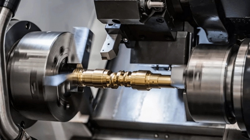
CNC turning machines are categorized based on how many axes they support. Each level offers a unique balance between complexity, flexibility, and cost.
A 2-axis CNC lathe features only X and Z axes. It performs standard turning and facing operations. These machines are compact, affordable, simple to operate, and ideal for mass production of basic cylindrical components.
Adding the C-axis transforms a basic lathe into a 3-axis turning center. With interpolated spindle control, users can index the part for limited milling, drilling, and engraving. This integration minimizes changeovers and supports light multi-process work.
By incorporating the Y-axis, a 4-axis machine allows off-center operations and angled features to be machined directly on the lathe. This eliminates the need for manual repositioning or transfer to a milling center, improving alignment precision and process integration.
The 5-axis CNC lathe, with both Y-axis and B-axis movement, provides unmatched versatility. It can machine compound angles, blend profiles, and contour complex surfaces without additional fixturing. Such machines are common in aerospace, oil and gas, and advanced automotive manufacturing.
While both CNC turning and milling rely on precise coordinate motion, their core principles differ.
| Feature | CNC Turning | CNC Milling |
|---|---|---|
| Primary Movement | Workpiece rotates | Cutting tool rotates |
| Primary Axes | X, Z (and optional C, Y, B) | X, Y, Z (and optional A, B, C) |
| Typical Parts | Cylindrical or conical | Prismatic or flat surfaces |
| Tool Path | Linear along part surface | 3D path around stationary part |
| Setup Time | Shorter | Longer |
| Speed | Faster material removal | More flexible geometries |
These differences highlight why modern shops often employ mill-turn centers—machines that merge both principles, optimizing flexibility and precision under one program.
In CNC turning, the spindle defines rotational motion while the turret holds and indexes cutting tools. Modern machines use servo-driven turrets synchronized with multiple axes for simultaneous turning, contouring, and milling.
Tool positioning systems can be configured for:
- Upper turret control: For general operations.
- Lower turret support: For dual-sided machining.
- Live tooling integration: For powered milling tools.
The combination of spindles, turrets, and tool changers enhances continuous production capability, reducing downtime and improving dimensional accuracy.
The integration of multiple axes brings significant operational benefits:
- Single-setup machining: Reduces time spent on manual repositioning.
- Precision improvement: Multi-axis synchronization minimizes cumulative errors.
- Reduced tooling costs: One setup serves multiple operations.
- Enhanced surface finish: Continuous cut transitions produce smoother surfaces.
- Shorter lead time: Streamlined workflow accelerates parts from prototype to production.
- Lower scrap rates: Consistent precision reduces material waste.
By combining these benefits, multi-axis CNC turning enhances both productivity and profitability.
Industries demanding precision and repeatability rely heavily on multi-axis CNC turning technology:
- Aerospace: Manufacturing of high-strength titanium shafts, turbine spindles, and engine housings.
- Automotive: Production of pistons, driveshafts, bearing housings, and gear blanks.
- Medical: Creation of surgical instruments, orthopedic screws, and dental implants.
- Defense: Precision elements for optical targeting and mechanical assemblies.
- Energy: Machining of valve components, drilling heads, and coupler threads.
- Electronics: Crafting miniature connectors, pins, and enclosures.
As industries demand tighter tolerances and shorter production cycles, the role of advanced-axis turning systems continues to expand.
When deciding on the right CNC turning system, manufacturers must balance several factors:
1. Part Geometry: Complex shapes benefit from more axes.
2. Material Type: Hard or composite materials require precise axis control.
3. Production Volume: High-volume runs might justify multi-axis automation.
4. Budget Constraints: Multi-axis machines represent higher capital investment.
5. Tool Accessibility: Toolpath simulation ensures collision-free motion.
6. Software Compatibility: CAD/CAM integration must support multi-axis commands.
Selecting the proper axis configuration ensures both process efficiency and return on investment.
As Industry 4.0 drives automation forward, CNC turning technology is evolving rapidly. Some emerging trends include:
- Hybrid additive-turning systems combining material deposition and removal.
- AI-assisted path optimization for real-time feed and speed adjustments.
- Digital twin simulations predicting axis interactions before production.
- Increased spindle synchronization for simultaneous front-and-back machining.
- Compact 6-axis configurations in mini turning centers for micro part production.
The integration of digitalization, smart sensors, and adaptive control keeps pushing CNC turning toward higher accuracy, reduced downtime, and better data-driven performance.
To understand CNC turning deeply, one must grasp the roles and relationships of its axes. The X-axis defines radial movement, Z-axis governs longitudinal travel, and C-axis facilitates precise spindle indexing. With additional axes such as Y, B, and sometimes A, the lathe evolves from a simple turning tool into a high-performance, multitasking machining center capable of producing geometrically complex components within a single setup.
Choosing the right axis configuration depends on part complexity, production goals, and budget. As modern manufacturing demands more accuracy and speed, multi-axis CNC turning remains essential for achieving excellent quality, shorter cycles, and optimized workflow in high-tech industries.
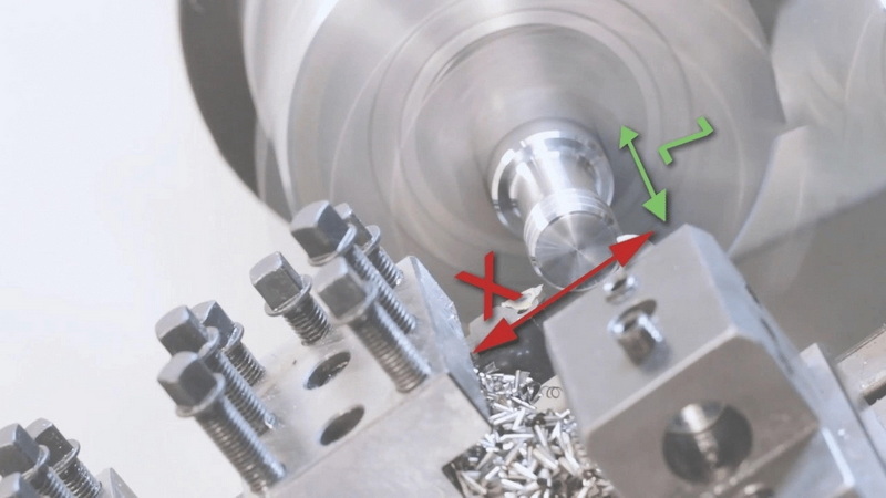
The X-axis controls tool movement toward or away from the workpiece's centerline, adjusting diameter, while the Z-axis manages longitudinal motion along the spindle, defining length and profile of the part.
The C-axis enables controlled spindle rotation for indexing or angular machining, allowing for secondary operations such as milling or drilling without separate setups.
The Y-axis allows the tool to move vertically, enabling off-center machining operations like milling or drilling holes that are not aligned with the main rotational axis.
Modern CNC turning centers range from basic 2-axis lathes to advanced 5-axis multitasking machines, each level offering greater flexibility and operational complexity.
It reduces setup time, boosts accuracy, allows production of intricate components in fewer operations, and increases overall system productivity and profitability.


