From idea to market-ready product, our NPI solutions make every stage easier, faster. Discover How We Help

Views: 222 Author: Tomorrow Publish Time: 2026-01-08 Origin: Site


Content Menu
● Understanding the Basics of CNC Turning
● What Exactly Is Slow Turning?
● Key Advantages of Slow Turning
>> Superior Dimensional Accuracy
>> Ideal for Difficult-to-Cut Materials
● Common Applications of Slow Turning
● Technical Principles Behind Slow Turning
● How to Set the Correct Parameters for Slow Turning
● Practical Tips for Optimizing Slow Turning
● Comparison: Slow Turning vs. High-Speed Turning
● Combining Slow Turning with Modern Technology
● FAQ
>> 1. What is the main goal of slow turning?
>> 2. Can slow turning be used for both roughing and finishing?
>> 3. How does material type affect slow-turning results?
>> 4. Does slow turning affect tool wear positively or negatively?
>> 5. Should coolant always be used in slow turning?
CNC turning is one of the most important machining processes in modern manufacturing. It shapes everything from precision mechanical parts to everyday components used across industries. While most discussions about CNC lathes focus on optimizing speed and productivity, there is a less-discussed yet essential technique known as slow turning.
Slow turning operates at reduced spindle speeds and feed rates to achieve exceptional surface finishes, tight dimensional control, and extended tool life. Though it may sound counterproductive in high-output manufacturing, this method is critical in high-precision industries where quality overrides cycle-time efficiency.
This article explores in depth what slow turning is, how it works, why it is used, and which best practices make it a valuable part of CNC operations.
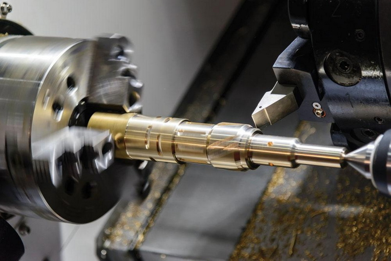
In a CNC (Computer Numerical Control) lathe, a cylindrical workpiece rotates at controlled speeds while a cutting tool removes material along different axes. The tool path, speed, and depth of cut are all programmed through the CNC controller, ensuring precise repeatability.
In turning operations, spindle speed, feed rate, and depth of cut are the three most influential parameters. Typically, machinists aim to optimize these for the shortest possible cycle time without sacrificing surface integrity. However, some materials, applications, or finishing requirements necessitate a much slower approach to prevent defects such as tool chatter, dimensional distortion, or thermal expansion — this is where slow turning becomes essential.
Slow turning refers to a machining process in which the rotational speed of the workpiece (RPM) and often the feed rate are significantly reduced compared to normal operating conditions. By lowering these speeds, the machinist ensures greater control over the cutting process, leading to high precision and consistent results.
Typical slow-turning speeds can range from 30% to 60% of standard cutting speeds, depending on the hardness of the material, the tool design, and surface finish requirements. For comparison, a standard operation on medium carbon steel might be performed at 300 SFM (surface feet per minute), while slow turning could be done at around 100–150 SFM.
Unlike roughing operations that prioritize material removal rates, slow turning is commonly used in the finishing stage, where the geometry and surface quality must meet strict engineering specifications.
A reduced cutting speed allows for finer tool control, generating small cutting forces and preventing vibration or chatter. This leads to smoother surfaces with consistency across the workpiece, often removing the need for secondary processes like grinding or polishing.
At lower speeds, thermal distortion and tool deflection diminish significantly. Maintaining consistent temperature in both the tool and the workpiece prevents micro-expansion or warping, allowing the production of parts within extremely tight tolerances — usually within 0.001 inches or less.
Excessive heat generated at high speeds is one of the primary causes of tool wear. Lowering the cutting speed reduces friction and thermal stress on the tool's cutting edge, prolonging tool life and decreasing the cost per part.
Hard-to-machine alloys such as titanium, stainless steel, or Inconel are challenging under high-speed conditions due to their low thermal conductivity and high hardness. With slow turning, the cutting temperature stays moderate, cutting forces are more manageable, and tool edge chipping is minimized.
Slow turning produces fewer vibrations and less dynamic load on machine components, ensuring consistent results even on long or slender parts where rigidity is a concern.
Slow turning is widely used across industries that require extreme precision, including:
- Aerospace: For turbine shafts, actuator sleeves, or hydraulic components that demand mirror-like finishes.
- Medical device manufacturing: Used for prosthetic joints, surgical tools, and implantable components where precision and durability are paramount.
- Automotive: For valve train parts, crankshafts, and other rotating components that must adhere to very tight tolerances.
- Optical and instrument engineering: Where surface finish quality directly affects performance, such as microscope mounts or camera lens housings.
- Mold and die making: Ensuring fine surface finishes that reduce polishing time and improve mold longevity.
Each of these sectors values part integrity, consistency, and dimensional predictability — all areas where slow turning excels.
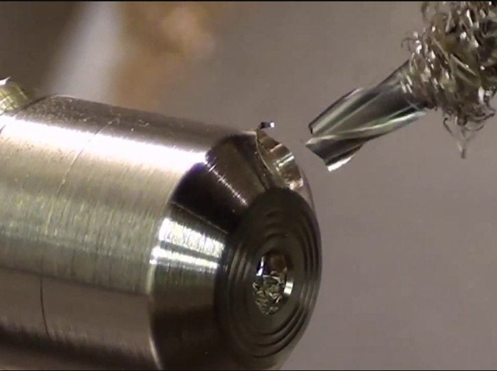
When the spindle speed decreases, several aspects of the machining physics also change:
1. Cutting Force Distribution: The slower the cutting edge moves, the more even and predictable the contact becomes, reducing chances of micro-fractures or premature edge wear.
2. Heat Transfer: A manageable heat gradient reduces thermal distortion in both the part and toolholder, improving dimensional control.
3. Material Flow: At reduced cutting speeds, chip formation becomes steadier, resulting in uniform chip thickness and fewer burrs at the edges.
4. Tool Wear Mechanisms: Slow turning lessens diffusion and oxidation wear modes, especially in carbide and CBN tools.
These improvements ultimately yield better surface integrity at both macro and micro scales.
There isn't a universal formula for slow turning. The optimal setup depends on the part geometry, material, tool coating, and machine rigidity. However, machinists can follow these guidelines:
- Reduce Surface Speed Gradually: Start with a 20–30% reduction from standard values and observe tool wear and chip condition.
- Adjust Feed per Revolution (f): Lower feed rates help reduce surface roughness. For example, 0.001–0.004 inches/rev is common in finishing.
- Minimize Depth of Cut (DOC): Shallow passes of 0.005–0.020 inches maintain dimensional accuracy while ensuring consistent contact.
- Use Proper Coolant Flow: Direct coolant precisely at the cutting zone to remove heat and extend tool life.
- Maintain Tool Sharpness: Dull tools generate excessive pressure and negate the benefits of low-speed cutting.
1. Always ensure machine rigidity. Any vibration or play in the tool post or chuck amplifies at low cutting speeds.
2. Use balanced tooling systems. Misaligned holders or uneven wear may cause surface marks and lead to out-of-tolerance dimensions.
3. Monitor spindle load. If torque fluctuations occur, they may indicate inconsistent chip formation or tool edge deterioration.
4. Test with dry and wet conditions. Some materials (like aluminum) perform better dry to prevent built-up edge formation, while heat-sensitive alloys need continuous cooling.
5. Implement in finishing passes. Combine fast roughing with slow finishing to achieve both productivity and precision.
While the method has numerous benefits, it also presents certain limitations:
- Reduced Productivity: The slower operation extends machining time, which can be a drawback in high-volume production.
- Chip Management: At very low speeds, chips may curl or adhere to the cutting edge. Effective chip breakers or oscillating tool paths help mitigate this.
- Potential for Built-Up Edge (BUE): In softer materials, inadequate cutting temperature may cause material adhesion to the tool, deteriorating surface finish.
- Coolant Dependency: Certain materials require constant cooling to avoid localized heat spots even in slow-speed operations.
Counteracting these issues requires experienced parameter tuning and sometimes custom tool geometry.
| Parameter | Slow Turning | High-Speed Turning |
|---|---|---|
| Cutting Speed | Low | High |
| Heat Generation | Very low | High |
| Surface Finish | Excellent | Moderate |
| Tool Life | Extended | Shorter |
| Dimensional Tolerance | Very tight | Moderate |
| Chip Formation | Controlled | Fragmented |
| Typical Application | Finishing tough materials | Roughing or volume production |
| Productivity | Lower | Higher |
The trade-off is evident: while high-speed turning boosts output, slow turning ensures precision and reliability.
With advancements in CNC machine control, hybrid approaches have become common. Many modern CNC programs use adaptive strategies — starting with fast roughing cuts, then automatically reducing RPM and feed rate for finishing passes.
Additionally, systems with real-time vibration monitoring and thermal compensation make slow turning more predictable and repeatable. Integrating these features improves both surface quality and process consistency, making slow turning a vital part of Industry 4.0 machining environments.
Even though slow turning operates at lower rotational speeds, safety must remain a top priority:
- Ensure chips do not wrap around rotating parts.
- Keep guards and coolant enclosures closed during operation.
- Stop the spindle before removing chips or adjusting tools.
- Use appropriate personal protective equipment (PPE) such as safety glasses and gloves.
- Regularly inspect the machine's spindle bearings, as long-duration operations at low speeds can affect lubrication patterns.
Slow turning on a CNC lathe is far from being a waste of cycle time — it is a precision-driven machining strategy. By carefully reducing spindle speed and feed rates, machinists gain enhanced control, smoother finishes, reduced tool wear, and dimensional stability impossible to match in high-speed operations.
While it may not suit mass-production environments, slow turning is indispensable where micron-level precision and surface perfection are required, particularly in aerospace, medical, and mold manufacturing industries. Understanding when and how to implement this method can elevate both the quality and reputation of any manufacturing operation.
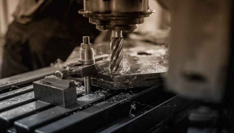
The primary goal is to achieve superior surface finishes and precise tolerances by reducing spindle speed and feed rates during machining.
It is primarily used for finishing operations because roughing at low speeds is inefficient and can increase production cost and time.
Materials with high hardness or low thermal conductivity (like titanium or Inconel) benefit most since slow turning reduces heat buildup and prevents tool wear.
It affects tool wear positively by minimizing friction, mechanical stress, and temperature, which together prolong the tool's usable life.
Generally yes, especially with difficult-to-cut alloys, but for non-ferrous materials like aluminum or brass, dry slow turning can sometimes produce cleaner finishes.


