From idea to market-ready product, our NPI solutions make every stage easier, faster. Discover How We Help

Views: 222 Author: Tomorrow Publish Time: 2026-01-02 Origin: Site


Content Menu
● How to Perform a Dry Run in CNC Machining
>> 2. Workspace and Fixture Preparation
>> 3. Machine Mode Configuration
● Key Parameters to Monitor During a Dry Run
● Benefits of Using the Dry Run Feature
● Common Mistakes During Dry Runs
● Best Practices for Safe and Efficient Dry Runs
● CNC Simulation vs. Physical Dry Run
● Industry Applications and Use Cases
● Addressing Advanced Dry Run Techniques
● FAQ
>> 1. What is the main purpose of a dry run in CNC?
>> 2. Does a virtual simulation replace the need for a dry run?
>> 3. How often should a dry run be performed?
>> 4. Can dry runs help optimize production time?
>> 5. Is there risk in performing dry runs?
CNC machining serves as one of the fundamental pillars of modern manufacturing, enabling precise and repeatable production of complex parts used across countless industries—from aerospace and automotive to medical and robotics. However, before any cutting tool touches material, operators must ensure that everything works exactly as intended. That's where the dry run comes in. This important process step allows machinists to verify, test, and refine CNC programs safely, dramatically reducing the risk of costly errors.
This article explains in depth what a dry run in CNC machining is, why it matters, how to perform it effectively, the common challenges encountered, and best practices to achieve maximum production reliability.
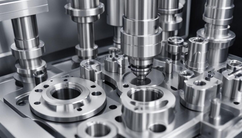
CNC, or Computer Numerical Control, uses coded instructions to automate the movement of machine tools like mills, lathes, and routers. These instructions, typically in G-code, control the tool's positioning, spindle speed, and feed rate to shape raw materials into precise components.
Because CNC machining operates with such tight tolerances—often within microns—any mismatch between the virtual design and real-world machine setup can cause serious problems. Even an unnoticed offset or coordinate error may lead to tool crashes, machine damage, or defective parts. Thus, performing a dry run helps bridge the gap between the digital and physical worlds, allowing machinists to confirm accuracy before starting production.
A dry run in CNC machining is a preliminary check in which the machining program is executed without cutting material. The machine follows the full programmed path, but the cutting tools either do not contact the workpiece or no material is present at all.
In this mode, machinists monitor machine actions—axis movements, tool changes, spindle activations, coolant commands, and safety stops—to ensure proper sequencing and orientation. Essentially, a dry run replicates every step of the machining process except the actual material removal.
Some operators also refer to this as simulation on machine, a physical validation that complements computer-based simulations. While digital CAM programs can highlight obvious collisions or travel errors, only a real dry run validates physical constraints like tool reach, fixture clearance, and spindle travel limits.
A dry run is not just a safety procedure—it's a strategic step that supports consistent quality and process optimization. Below are major reasons why dry runs remain indispensable to modern CNC workflows:
1. Detecting Program Errors:
Even the most experienced programmers can make syntax mistakes or logic errors in G-code. A dry run visually confirms that each line of the program executes correctly.
2. Preventing Machine and Tool Damage:
CNC tools, especially carbide or diamond-coated types, are costly. By detecting potential crashes early, dry runs protect tools, fixtures, and spindles from damage worth thousands of dollars.
3. Improving Setup Accuracy:
When testing new fixtures or coordinate systems, a dry run ensures proper alignment and offset before production begins. It helps confirm that the defined zero-point (G54, G55, etc.) matches the physical workpiece position.
4. Enhancing Operator Confidence:
New operators can observe how a program behaves in real time, building familiarity without the stress of potential damage.
5. Reducing Waste:
Since no material is cut, any discovered error results in no lost stock or scrapped components, directly improving cost efficiency.
6. Verifying Safety Systems:
Safety interlocks, limit switches, and axis constraints can be confirmed during dry runs, ensuring the machine responds correctly to programmed movements.
The procedure for conducting a dry run depends on machine brand and model (Fanuc, Siemens, Haas, etc.), but the core approach remains consistent across platforms.
Before initiating the dry run, carefully check the G-code for:
- Correct tool numbers and offsets
- Proper feed and spindle speeds
- Safe retract heights and clearance moves
- Correct use of coolant and pauses
Modern CAM systems often simulate tool paths on-screen, allowing preliminary error detection. However, visual inspection on the actual CNC interface remains critical.
- Clean the machine bed and ensure no loose tools or components remain.
- Verify that all tools are installed securely and match the program list.
- Double-check that the workholding device (vise, chuck, or fixture) is mounted properly.
- Lift the spindle tool several millimeters above the workpiece surface or remove the part completely.
Switch the CNC control into Dry Run Mode or Single Block Mode. Both are designed to let users run programs safely:
- Dry Run Mode: Runs the entire program with controlled speed overrides.
- Single Block Mode: Executes one line of code at a time, allowing detailed inspection.
Run the program slowly, often at 10–25% of normal feed and rapid rate. Carefully monitor every movement. Ensure that tool changes happen at the correct locations and that no axes exceed their limits.
If an issue arises, stop immediately, edit the G-code, and rerun the dry check. Sometimes multiple dry runs are necessary to fine-tune paths before approving a full production cycle.
To maximize the dry run's effectiveness, machinists must pay attention to several details simultaneously:
- Toolpath accuracy: Verify that all approach and retract movements match design intent.
- Z-height clearance: Ensure adequate spacing in vertical movements to prevent surface contact.
- Axis limitations: Confirm none of the programmed moves exceed the machine's physical travel capacity.
- Feed rates: Adjust override controls to slow motion for detailed observation.
- Tool length offsets: Ensure TLOs and work coordinate systems correspond correctly.
By carefully evaluating these parameters, the machinist ensures that subsequent real machining will proceed efficiently and safely.
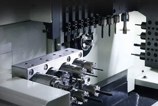
Incorporating dry runs into daily CNC operations yields both immediate and long-term benefits:
- Enhanced Equipment Longevity:
Preventing unexpected collisions extends spindle life and reduces mechanical wear.
- Optimized Cycle Times:
Observing dry runs often reveals inefficient tool transitions or redundant moves, which can then be removed or optimized before production.
- Training and Skill Development:
New staff can learn program timing, machine behavior, and safe operating procedures from observing dry runs.
- Predictive Maintenance:
Inconsistencies detected during dry runs often hint at lubrication or calibration issues, providing early warning before they escalate.
- Improved Process Reputation:
Delivering consistent quality through verified procedures improves customer trust in manufacturing reliability.
Despite its name, a poorly executed dry run can still cause problems. Frequent errors include:
- Running the simulation too fast and overlooking subtle tool collisions.
- Forgetting to engage the correct coordinate system, leading to off-axis movement.
- Misinterpreting machine zero with program zero, a common rookie mistake.
- Ignoring alarm codes or controller warnings.
- Failing to document or apply changes after verification.
Each dry run should be approached with the same precision mindset as actual machining. The more thoroughly an operator reviews the simulated operation, the more confident the production cycle will be.
Mastering the dry run process involves strict attention to both technique and environmental control. Below are proven best practices:
1. Always start slow: Begin at minimal rapid and feed override settings, increasing speed once paths are confirmed safe.
2. Maintain proper lighting and visibility: Sufficient light ensures operators can clearly view the machine interior.
3. Keep one hand near the emergency stop: Every machinist should be prepared to halt the machine instantly.
4. Use mirror tool setups: If testing symmetrical parts, mirror paths in simulation before switching sides physically.
5. Record all modifications: Each correction made during dry runs should be noted in setup sheets for reproducibility.
Following these principles minimizes risk while achieving precision.
Modern CAM software (such as Fusion 360, Mastercam, or Siemens NX) offers powerful 3D simulation tools to check for collisions and program flow. They generate animated previews showing the tool removing material layer by layer, highlighting errors in feed rates or travel limits.
A true dry run physically tests mechanical behavior. Unlike software, it factors in machine wear, fixture alignment, and real spindle behavior. Only during physical dry runs can operators assess subtle issues like vibration or clearance problems near clamps.
The most effective approach combines virtual and physical validation. First, simulate the program digitally on the computer to correct coding or model errors. Then, conduct a full physical dry run on the machine before production.
Dry runs play a vital role across various manufacturing sectors:
- Aerospace: Precision parts require zero tolerance for error; dry runs validate complex multi-axis paths before machining titanium or Inconel.
- Automotive: Short production cycles benefit from early error detection, preventing downtime on assembly lines.
- Medical tooling: Custom devices need flawless geometry; dry runs confirm accuracy before cutting biocompatible materials.
- Industrial molds: Mold cavities are often expensive to rework; testing toolpaths reduces defects.
- Prototyping: Before mass production, engineers ensure prototype dimensions align with intended design.
Through these applications, dry runs enhance both precision and predictability on a global manufacturing scale.
For complex multi-axis machining, advanced dry run strategies further enhance verification:
- Machine coordinate mapping: Testing 4th or 5th axis rotation to ensure clearance from fixtures.
- Adaptive feed control: Adjusting program feeds based on dry run observation to remove non-cutting downtime.
- Toolpath optimization through macros: Using macro variables (like G65 codes) to create adaptive dry run conditions where changes can be input easily before production.
Such advanced use transforms the dry run from a simple safety check into a continuous improvement tool.
While a dry run takes time, its financial benefits are significant:
- A single machine crash can cost thousands in repairs.
- Tool breakage increases both material costs and production delays.
- Rejecting a batch of out-of-spec parts wastes expensive stock.
By investing minutes in a careful dry run, manufacturers save hours—or days—of rework. Over time, dry runs directly contribute to higher efficiency, lower defect rates, and more predictable profit margins.
A dry run in CNC machining isn't just an optional safeguard—it's an essential part of precision manufacturing. It verifies toolpaths, protects costly machinery, prevents waste, and instills confidence among machinists. In an era driven by automation and complexity, embracing thorough dry run procedures bridges the gap between digital design and flawless reality. By integrating simulation verification, careful observation, and diligent record-keeping, manufacturers can achieve both safety and excellence on the shop floor.
The primary purpose is to verify a CNC program's safety and accuracy without cutting material, reducing the risk of crashes and production errors.
No. Simulations catch coding errors but not physical variances such as fixture offsets or spindle clearance. Physical dry runs verify these real-world conditions.
Dry runs are necessary whenever running a new program, introducing new tooling, changing setups, or adjusting coordinate systems before production.
Yes. Many machinists discover redundant tool motions or inefficient feeds during dry runs, allowing cycle-time improvements before actual machining.
Minimal, as long as the operator follows safety protocols like using slow speeds, disabling coolant, and staying alert near the emergency stop button.


