From idea to market-ready product, our NPI solutions make every stage easier, faster. Discover How We Help

Views: 222 Author: Tomorrow Publish Time: 2025-11-30 Origin: Site


Content Menu
● Understanding CNC Turning Programming
● Steps to Create a CNC Turning Program
>> Calculate Tool Paths and Parameters
>> Load and Simulate the Program
>> Trial Cutting and Fine-tuning
● Key G-code Commands used in Turning
● Advanced CNC Turning Techniques
>> Intelligent ID and OD Roughing
>> C-Axis Programming and Live Tooling
>> Dynamic Motion and High-Speed Machining
>> Multi-Tool and Adaptive Machining
>> Parametric and Macro Programming
● Tips for Successful CNC Turning Programs
● FAQ
>> 1. What software can I use to create CNC turning programs?
>> 2. What is the difference between G00 and G01 commands?
>> 3. How important is tool offset in CNC turning?
>> 4. Can I create a CNC turning program without prior programming experience?
>> 5. How do I verify my CNC turning program before machining?
Creating a CNC turning program is a detailed process that transforms part designs into actionable instructions for a CNC lathe machine. This process involves interpreting part drawings, calculating tool paths, writing G-code, and verifying the program through simulation and trial cutting. Mastery of this skill is essential for maintaining precision and efficiency in manufacturing.
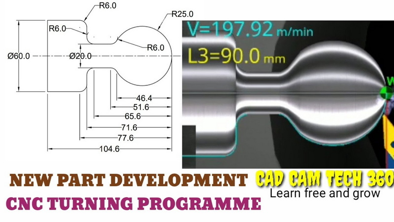
CNC turning programming uses G-code, a standardized programming language that controls machine movement, spindle rotation, cutting speeds, and tool changes. Through G-code, programs communicate how to cut, shape, and finish parts accurately. Programming can be done manually or with the assistance of CAM (Computer-Aided Manufacturing) software, which automates tool path generation for complex parts. Successful programming transforms design blueprints into real objects by detailed, stepwise machine commands.
Thoroughly review the engineering drawing to understand the geometry, dimensions, tolerances, and special requirements of the part. This step determines the machining strategy, tooling selection, and order of operations. Important features to note include diameters, lengths, surface finishes, grooves, threads, and tapers.
Next, calculate the exact tool paths, including start and end points, cutting depths, and arcs. Also, determine appropriate spindle speeds and feed rates based on the material and tooling conditions to optimize performance and tool life. This stage requires knowledge of material machining properties and cutting dynamics.
Using G-code syntax, write the program specifying operations such as facing, turning, grooving, and threading. The typical structure includes:
- Program number and initialization codes
- Tool selection and offset definitions
- Spindle speed commands and coolant controls
- Sequential machine movements using rapid (G00) and cutting (G01) commands
- Circular interpolations with G02/G03 for arcs
- Machining cycles like roughing, finishing, and threading
- End of program commands
Attention to detail in coding ensures accurate interpretation by the CNC controller.
Transfer the G-code to the CNC lathe via USB, network, or manual input. Many modern machines have simulation modes that graphically visualize tool paths, helping validate the program and detect possible errors before actual cutting.
Conduct a dry run or cut on sample material. Measure the workpiece to verify dimensional accuracy and surface finish. Adjust feeds, speeds, or tool offsets as needed to correct errors. Repeat until results meet specifications.
- G00: Rapid positioning without cutting
- G01: Linear interpolation for cutting moves
- G02/G03: Circular interpolation clockwise/counterclockwise
- G28: Automatic return to machine home
- M03/M04: Spindle on clockwise/counterclockwise
- M05: Spindle stop
- M08/M09: Coolant on/off
Using these commands effectively controls machine behavior during turning.
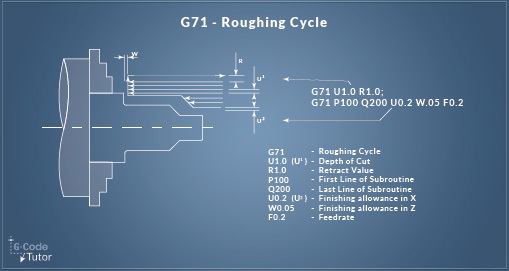
This technique focuses on efficient rough material removal while preserving tool life. Software such as Mastercam supports roughing operations that automatically create optimized tool paths, reducing cycle time and extending cutter durability.
C-axis control enables the spindle to index and synchronize with the turret for machining complex contours, cross-holes, or threading. Live tooling adds milling capabilities on a turning center, allowing drilling and tapping without part removal, massively reducing setup time and improving accuracy.
Dynamic Motion™ and high-speed machining (HSM) techniques maintain consistent chip load by balancing feed rate and spindle speed, minimizing tool wear and improving surface finish. These methods reduce cycle time and increase machining efficiency, especially in hard materials.
Using multiple tools within one setup streamlines roughing and finishing passes. Adaptive machining employs real-time monitoring and feedback to dynamically adjust cutting parameters, handling variations in material hardness or casting defects effectively.
Parametric programming uses variables and equations for flexible code adaptable to different sizes or features, enhancing efficiency when making similar parts. Macros automate repetitive code blocks, saving time and reducing human error.
- Double-check tooling and workpiece setups for safety and precision.
- Use tooling offsets to compensate for wear and dimensional variations.
- Comment code clearly to facilitate troubleshooting and future edits.
- Validate programs through simulation and trial runs before production.
- Optimize feeds and speeds iteratively to balance quality and throughput.
Making a CNC turning program requires comprehensive knowledge of part design, G-code commands, and machining principles. Advances like C-axis programming, live tooling, and adaptive machining expand capabilities beyond basic operations. A systematic approach from drawing analysis to trial cutting ensures accurate, cost-effective machining, consistently producing high-quality turned parts.
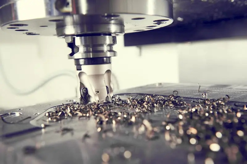
CAD software for design and CAM software like Mastercam, Fusion 360, and SolidWorks CAM are widely used for automated tool path generation.
G00 moves the tool rapidly without material engagement, while G01 moves the tool linearly at a controlled feed rate for cutting.
Tool offsets adjust for tool length and diameter variations, crucial for maintaining machining accuracy and compensating for tool wear.
Yes, modern conversational programming software and CAM tools make programming accessible without extensive G-code knowledge.
Use machine simulation modes or dry runs followed by test cuts and precision measurements to verify and refine the program.
[1](https://www.yumeihardware.com/blog/how-do-you-program-a-cnc-machine-a-step-by-step-guide/)
[2](https://tmc-technologies.com/cnc-lathe-programming/)
[3](https://machiningconceptserie.com/cnc-toolpath-advanced-techniques/)
[4](https://www.sigmatechnik.com/cnc-factory/mastering-cnc-turning-programming-a-step-by-step-tutorial)
[5](https://www.supercncmachine.com/top-10-cnc-lathe-machine-programming-techniques/)
[6](https://www.youtube.com/watch?v=Qqg-aoVIs_8)
[7](https://www.makerverse.com/resources/cnc-machining-guides/best-practices-designing-for-cnc-turning/)
[8](https://www.goodwin.edu/enews/cnc-machining-techniques/)
[9](https://www.youtube.com/watch?v=4xNMYLPE_jM)
[10](https://www.practicalmachinist.com/forum/threads/cnc-lathe-programming.441770/)


