Language


Views: 222 Author: Tomorrow Publish Time: 2025-11-30 Origin: Site


Content Menu
● Understanding RPM in CNC Turning
● Basic Formula for RPM Calculation
● Step-by-Step RPM Calculation Process
● Considerations for Feed Rate and Chip Load
● Advanced Factors Affecting RPM Calculation
● Practical Tips for RPM Optimization
● Common RPM Calculation Formulas Summary
● Feed Rate and Surface Finish
● Safety and Efficiency Considerations
● FAQs
>> 1. How to determine the correct cutting speed for CNC turning?
>> 2. What is the relationship between RPM and feed rate in CNC turning?
>> 3. How can I calculate spindle speed in imperial units?
>> 4. Why is chip load important when calculating RPM?
>> 5. Can I adjust RPM during machining?
Calculating RPM (Revolutions Per Minute) in CNC turning is essential for optimizing machining performance, tool life, and workpiece quality. RPM determines how fast the spindle rotates and directly influences cutting speed and feed rate, which affect the precision and efficiency of the turning process. This article explains the principles, formulas, and practical steps to calculate RPM accurately in CNC turning operations.

RPM refers to the number of rotations the spindle makes per minute. In CNC turning, it controls the speed at which the cutting tool engages the workpiece. Choosing the correct RPM is critical because too high a speed can cause tool overheating and premature wear, while too low a speed may reduce cutting efficiency and surface finish quality. RPM calculation depends on the material, tool diameter, and desired cutting speed.
The fundamental formula to calculate RPM in CNC turning involves the cutting speed and the diameter of the workpiece or cutting tool. The formula used is:
RPM=(CuttingSpeed×1000)/π×Diameter
- Cutting Speed (V): Usually given in meters per minute (m/min)
- Diameter (D): Diameter of the workpiece or tool in millimeters
- π (Pi): A constant approximately equal to 3.1416
This formula provides the spindle speed in revolutions per minute needed to maintain the desired cutting speed during turning.[11][12]
When using imperial units, the formula adjusts to use feet per minute (SFM) for cutting speed and inches for diameter:
RPM=(CuttingSpeed×4)/Diameter
- Cutting Speed in feet per minute (ft/min)
- Diameter in inches
This formula is a simplified version often used for quick calculations in countries using imperial measurement systems.[12]
1. Determine the cutting speed: Refer to material-specific cutting speed charts. For example, steel may have a cutting speed of 20-30 m/min if using high-speed steel tools.
2. Measure the diameter: Measure the diameter of the workpiece where the cutting occurs.
3. Plug values into the formula: Use the metric or imperial formula depending on your unit system.
4. Calculate RPM: Perform the calculation to find the spindle speed in revolutions per minute.
For example, if the cutting speed is 30 m/min and the diameter is 50 mm, the RPM calculation is:
RPM=30×1000/3.1416×50≈191RPM
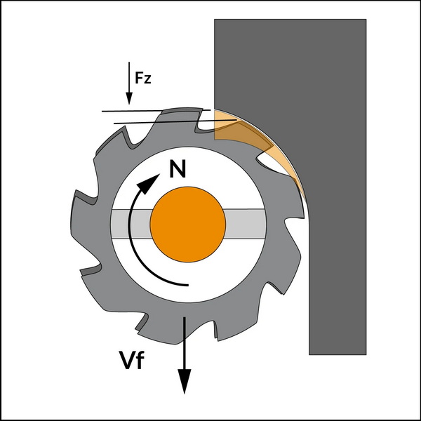
RPM is linked closely to feed rate, which is the distance the tool advances in one revolution of the spindle. Feed rate calculation involves multiplying the RPM by the feed per revolution (the distance tool moves per revolution) and the number of tool flutes if applicable. Proper feed rate ensures good surface finish and efficient material removal without overloading the tool.
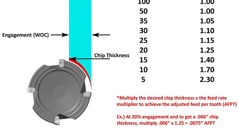
Chip load, the thickness of the chip removed by each cutter tooth, also influences feed and RPM choice. Different materials and cutter sizes require specific chip load values to avoid tool breakage or poor surface quality.[12]
Beyond the basic formulas, several advanced factors can affect RPM calculation in CNC turning for optimized results:
- Material Hardness and Type: Harder materials like stainless steel require slower RPM to reduce heat and prolong tool life, while softer materials like aluminum allow higher RPM for faster machining.
- Tool Geometry: The tool's shape, coating, and diameter impact cutting forces and optimal RPM. For example, tools with a high helix angle or sharp edges can accommodate different RPM ranges.
- Machine Capability: The CNC machine's maximum spindle speed and rigidity can limit feasible RPM ranges. It is crucial to match RPM settings with machine specifications.
- Coolant Usage: Applying coolant can help maintain higher RPM by reducing cutting temperature and improving chip evacuation.
- Cutting Depth and Feed Adjustments: Higher depths of cut or feed rates may require RPM modifications to avoid tool overload or poor surface finish.
- Start with recommended cutting speeds from tool manufacturers tailored to the material.
- Adjust RPM based on observed tool wear, cutting noise, vibration, and surface finish.
- Use CNC machine data logging or simulation software to test optimal RPM settings before production runs.
- Consider environmental factors such as temperature and humidity, which can slightly influence machining conditions.
| Unit System | Formula | Cutting Speed Units | Diameter Units |
|---|---|---|---|
| Metric | RPM=1000×V=π×D1000 | meters per minute | millimeters |
| Imperial | RPM=4×CS=D4 | feet per minute | inches |
| Alternative | RPM=SFM×12=π×Diameter | Surface feet / min | inches |
These formulas are central to spindle speed calculation and can be adapted depending on specific machining setups and materials.[13][12]
Feed rate (inches or millimeters per minute) works in tandem with RPM to control the amount of material removed and surface finish quality. Feed rate is calculated as:
FeedRate=RPM×NumberofTeeth×ChipLoad
Where chip load is the thickness of the material removed by each cutting edge. Optimizing feed rate alongside RPM helps avoid tool overload, chatter, and poor surface finish.[3]
Proper RPM settings extend tool life by minimizing heat generation, reducing wear, and preventing mechanical shock. Operating at incorrect RPM can cause premature tool failure, increase production costs, and reduce overall part quality. Tool life is influenced by:
- Material and hardness
- Tool coating and geometry
- Cooling and lubrication
- Proper RPM and feed rate combination
Exceeding recommended RPM can damage the machine, tool, and workpiece. Tools may break or eject debris, posing operator safety risks. Conversely, too low RPM reduces efficiency and can cause rubbing or poor chip formation. Maintaining proper RPM contributes to safe, efficient, and cost-effective CNC turning operations.
Calculating RPM correctly in CNC turning is fundamental for machining efficiency, tool life, and product quality. Using the cutting speed and diameter-based formulas allows machinists and programmers to set the spindle speed precisely. Considering advanced factors such as material hardness, tool geometry, machine capability, and cooling can further optimize the process. Proper RPM calculation combined with feed rate adjustment ensures superior machining results, longer tool life, and safe operation. Mastery of RPM calculation is a core skill in CNC machining that leads to operational excellence.
Cutting speed depends on the material type and tool used. Consult materials and tooling charts for recommended speeds, which vary for metals and tool types like high-speed steel or carbide.
RPM controls spindle speed, while feed rate determines tool movement per revolution. Feed rate is calculated by multiplying RPM by feed per revolution, influencing surface finish and machining time.
Use the formula RPM = (Cutting Speed (ft/min) × 4) / Diameter (inches) to get spindle speed in RPM when measurements are in imperial units.
Chip load affects the thickness of material removed per cutter tooth. Incorrect chip load may cause tool wear or part damage, so RPM and feed must align with recommended chip loads.
Yes, adjusting RPM to match tool wear, material hardness, or surface finish requirements helps maintain machining quality and tool life.
[1](https://www.sigmatechnik.com/cnc-factory/how-to-calculate-rpm-for-cnc-turning-a-step-by-step-guide)
[2](https://www.longshengmfg.com/how-to-calculate-rpm-in-cnc-turning/)
[3](https://tmc-technologies.com/how-to-calculate-speed-and-feed-for-cnc-lathe/)
[4](https://www.dajinprecision.com/news/85--cnc-turning-cutting-speeds--feeds-how-to-calculate-speeds-and-feeds-for-cnc--dajin-precision)
[5](https://www.ctemag.com/articles/cutting-time-facing)
[6](https://www.cnccookbook.com/feeds-speeds/)
[7](https://www.dapra.com/resources/milling-formulas)
[8](https://www.3erp.com/blog/cnc-machining-parameters/)
[9](https://zero-divide.net/fswizard)
[10](https://www.youtube.com/watch?v=pYxI7uE0iN0)
[11](https://www.asianstarcnc.com/cnc-turning-factory/mastering-cnc-turning-calculations-essential-formulasapplications)
[12](https://jetcrafted.com/how-to-calculate-rpm-in-cnc-turning/)
[13](https://www.kennametal.com/us/en/resources/engineering-calculators/miscellaneous/speed-and-feed.html)


