From idea to market-ready product, our NPI solutions make every stage easier, faster. Discover How We Help

Views: 222 Author: Tomorrow Publish Time: 2025-11-24 Origin: Site


Content Menu
● What Is Feed Rate in CNC Turning?
● The Basic Formula for Feed Rate
● How to Calculate the Spindle Speed (N)
● How to Determine Feed per Revolution
● Advanced Feed Rate Equation Considering Tool Teeth and Chip Load
● Factors Influencing Feed Rate Adjustments
● Best Practices for Feed Rate Calculation
● FAQ About CNC Turning Feed Rate
>> 1. What is the difference between feed rate and spindle speed?
>> 2. How is the spindle speed calculated for turning?
>> 3. Why is chip load important in feed rate calculation?
>> 4. Can feed rate be too high or too low?
>> 5. How do machine and tool conditions influence feed rate?
Calculating the feed rate for CNC turning is a fundamental task to ensure efficient, accurate, and high-quality machining operations. The feed rate determines how fast the cutting tool moves along the rotating workpiece, affecting the surface finish, tool life, and overall machining productivity. Proper calculation involves an understanding of key parameters like spindle speed (RPM), feed per revolution, and the workpiece diameter.

Feed rate in CNC turning refers to the linear speed at which the cutting tool advances relative to the workpiece. It's usually measured in millimeters per minute (mm/min) or inches per minute (IPM). The feed rate is crucial because it controls the thickness of the chip removed with each tool rotation and directly impacts quality and tool wear. Setting the optimal feed rate balances productivity and machining precision.
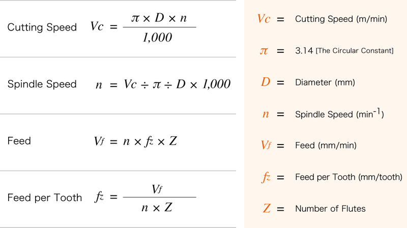
The feed rate $$ F $$ in CNC turning is calculated using the formula:
$$
F = N \times f
$$
where:
- $$ F $$ = Feed rate (mm/min or IPM)
- $$ N $$ = Spindle speed or rotational speed of the workpiece (RPM)
- $$ f $$ = Feed per revolution (mm/rev or in/rev), the linear movement of the tool per spindle revolution
The feed per revolution $$ f $$ varies depending on the material, tool type, and machining conditions. It dictates how much the tool moves during each rotation of the workpiece.
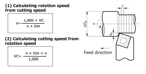
The spindle speed $$ N $$ is determined by the cutting speed $$ V_c $$ of the material and the diameter of the workpiece $$ D $$:
$$
N = \frac{1000 \times V_c}{\pi \times D}
$$
where:
- $$ N $$ = spindle speed (RPM)
- $$ V_c $$ = cutting speed in meters per minute (m/min)
- $$ D $$ = diameter of the workpiece in millimeters (mm)
- $$ \pi \approx 3.1416 $$
Cutting speed $$ V_c $$ is material-specific and tool-specific and usually found in machining handbooks or manufacturer datasheets.
Feed per revolution depends on:
- Material hardness and machinability
- Tool geometry (shape, size, number of cutting edges)
- The type of cut (roughing vs. finishing)
- Desired surface finish and tool life
Typical feed per revolution values range from 0.05 mm/rev for finishing to 0.5 mm/rev or higher for roughing. Machinists often start at manufacturer recommendations and adjust based on actual cutting conditions.
For tools with multiple cutting edges (teeth), the feed rate formula extends to:
$$
F = N \times T \times CL
$$
where:
- $$ F $$ = Feed rate (mm/min or IPM)
- $$ N $$ = Spindle speed (RPM)
- $$ T $$ = Number of teeth or cutting edges on the tool
- $$ CL $$ = Chip load per tooth (thickness of material removed by each tooth per revolution)
This formula is more applicable in milling and certain types of turning when the tool has multiple cutting edges. For turning with single-point tools, the simpler $$ F = N \times f $$ often suffices.
Let's say you have:
- Workpiece diameter $$ D = 50 $$ mm
- Cutting speed $$ V_c = 150 $$ m/min
- Feed per revolution $$ f = 0.2 $$ mm/rev
Step 1: Calculate spindle speed $$ N $$:
$$
N = \frac{1000 \times 150}{3.1416 \times 50} \approx 955 \text{ RPM}
$$
Step 2: Calculate feed rate $$F$$:
$$
F = 955 \times 0.2 = 191 \text{ mm/min}
$$
So, the CNC turning feed rate is approximately 191 mm/min.
Several factors require tuning feed rates in practical applications:
- Material characteristics: Harder materials require slower feed to reduce tool wear.
- Tool condition: Worn tools need slower feeds.
- Machine rigidity: Less rigid machines may require reduced feed rates to prevent chatter.
- Cutting environment: Use of coolant can allow increased feeds.
- Depth of cut and width of cut: Heavier cuts generally require slower feed to maintain stability.
Using a starting feed rate based on calculations followed by empirical adjustments helps optimize machining.
- Always reference tooling manufacturer data for feed and speed ranges.
- Use conservative values for unfamiliar materials or setups.
- Check machine capabilities for maximum feed and spindle speed.
- Use CNC machine feedback and monitoring systems to adapt feeds for optimal performance.
- Regularly inspect tool wear to adjust feed when necessary.
Calculating feed rate for CNC turning revolves around determining the spindle speed from cutting speed and workpiece diameter, then multiplying by the feed per revolution or chip load, adjusted for the number of tool teeth if applicable. This ensures efficient material removal while protecting tool life and maintaining quality. By understanding and applying these principles along with real-world adjustments, machinists can achieve optimized CNC turning operations.
Feed rate is the linear speed at which the tool moves along the workpiece (mm/min or IPM), while spindle speed (RPM) is the rotational speed of the workpiece spindle. Feed rate calculation depends on spindle speed and feed per revolution.
Spindle speed is calculated using cutting speed and workpiece diameter with the formula $$N = \frac{1000 \times V_c}{\pi \times D}$$, where $$V_c$$ is cutting speed in m/min, and $$D$$ the diameter in mm.
Chip load defines the thickness of material removed by each cutting edge per revolution. It directly affects tool life, surface finish, and machining efficiency.
Yes, too high feed rates cause poor surface finish and rapid tool wear; too low feed rates can reduce productivity and cause rubbing instead of cutting.
Less rigid machines and worn tools require reduced feed rates to avoid vibration and damage, while coolant and proper tooling setups can enable higher feed rates for better productivity.
[1](https://tmc-technologies.com/how-to-calculate-speed-and-feed-for-cnc-lathe/)
[2](https://www.longshengmfg.com/cnc-turning-speed-feed-rpm-calculation-method/)
[3](https://cncshop.com/pages/calculating-feeds-and-speeds)
[4](https://www.kennametal.com/us/en/resources/engineering-calculators/miscellaneous/speed-and-feed.html)
[5](https://www.youtube.com/watch?v=wI4eGleVTXk)
[6](https://www.reddit.com/r/CNC/comments/dzv34o/how_to_calculate_feeds_and_speed/)
[7](https://zero-divide.net/fswizard)
[8](https://www.youtube.com/watch?v=zzzIpC39WUg)
[9](https://www.camaster.com/cnc-router-calculating-feeds-and-speeds/)
[10](https://www.cnccookbook.com/feeds-speeds/)


